Calaos Rules System #2

Lets continue this series on the Rule system. Today we are going to create some more advanced rules, and explain how it works under the hood.

Control multiple IO in sync

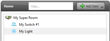
In this example we have two light in a room. And we want that when we press the switch both light goes ON simultaneously.

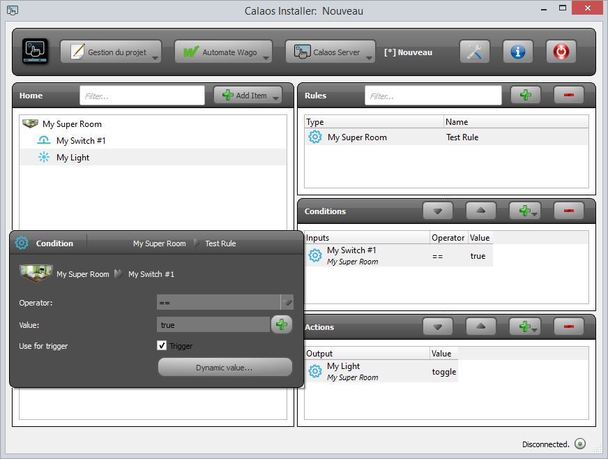
A basic approach of doing the rule would be:

That will work when both lights are synced, but the problem that need to be solved is that when lights are controlled directly (from calaos_home or calaos_mobile), and then pressing the switch, they could be out of sync. (first is ON and the second is OFF). The only way to put both lights in sync again is to do it manually. No so smart!

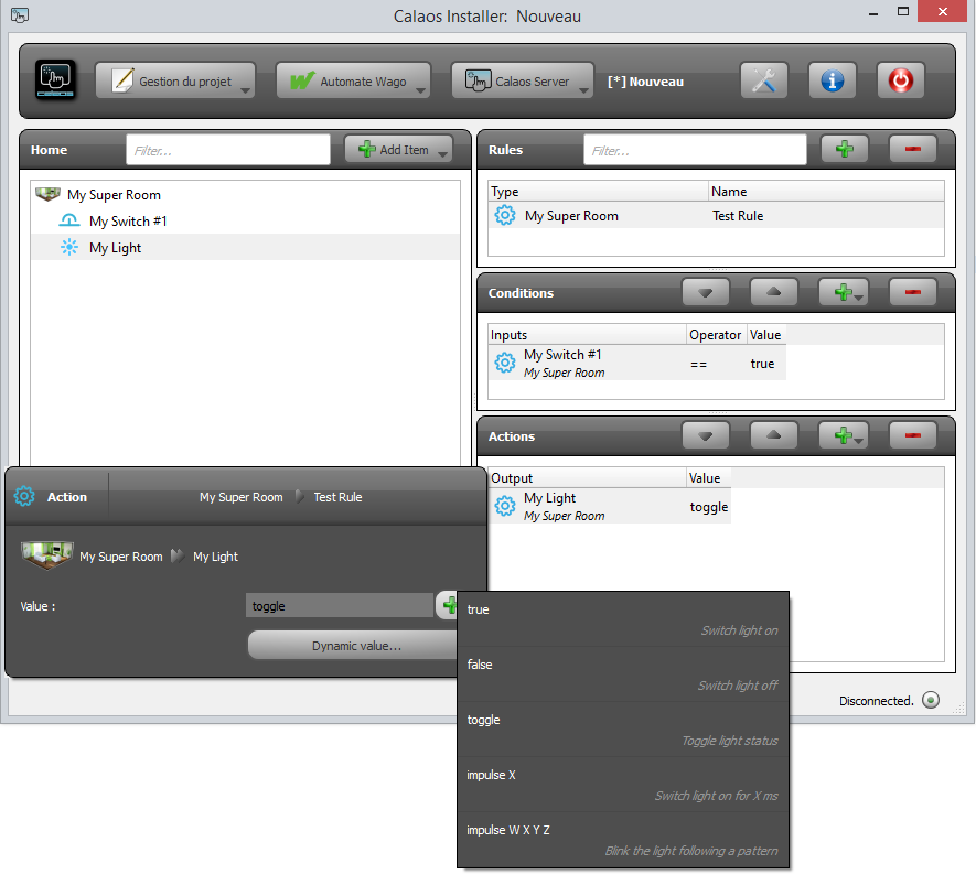
As you saw in the action popup, you can choose an action for the light from a predefined static list. Possible actions are for ex: toggle, true, false, … But there is a button right under the action, Dynamic value. This is where you can choose a value from an other IO. In concrete terms, after clicking the button you will be able to choose an IO, and when the action is executed, the value will be extracted from the selected IO.

ci_02


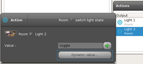
Lets do that for the Light 2. So now in our example the first action is to toggle the state of the first light, and then assign that new state to the second light.
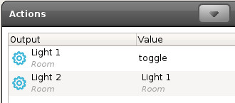
Now with such a rule, if the lights are not in sync, the second light will automatically be set at the same state. Of course this example can be repeated with other type of IO, like shutters. It’s extremely powerful when controlling multiple shutters with just one button.

Other approach

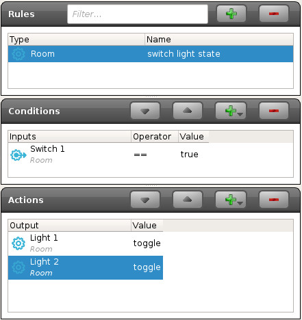
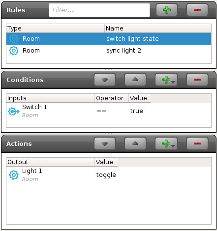
There is another way to sync both lights, by using a second rule. This time we will use a rule to toggle the state of the first light:

ci_04

And a second rule with a condition that checks for the Light 1 state change. If the state changes, we update the state of the second light from the first light.

ci_05

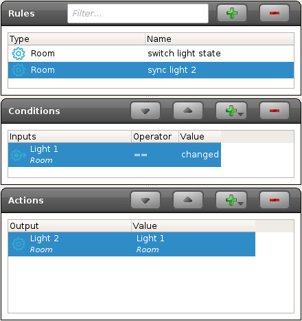
The fundamental difference between the two solutions exposed here is that the sync is done everytime the state of Light 1 changes, even when you control the light from the user interfaces. In the first solution that’s not the case, the second light is only synced when you press the switch.

The second approach is good when you need to link multiple outputs. You only need to do an action on the first IO, and the second will be updated automatically.


Calaos and 1-Wire

1-Wire is a communication bus, wich uses only 1 wire^W 2 or 3 wires for communications between slaves and a master. One of the most common 1wire module is a temperature sensor, the DS18b20. This is already calibrated, directly on the production line, and like all 1wire chips it contains a unique identifier.

The DS18B20 has an operating temperature range of -55°C to +125°C. And the sensor is accurate to +/-0.5°C over the range of -10°C to +85°C. And it’s cheap, you can find it for less than 1€. You can even found a waterproof version of this sensor.

As it uses only 2 or 3 wires, it’s easy to add this kind of sensor in a house or an appartment, you only need a pair of twisted wires, like the one we found in ethernet or telephony cables.

On the home automation box, you need an hardware interface to communicate with the sensor, and a program to talk with this interace. Calaos and more specifically calaos-os integrate such sofware : owfs

For the hardwre interface, you have 3 choices. If your home automation box, is a Raspberrypi or an electornic card with GPIOs, you may use the w1 linux kernel driver. It emulates a 1wire master with a single gpio. The only thing you have to do is to connect 1-wire sensors to the Rpi GPIO like here :

1wire

As you can see, 1wire is a bus so we can chain temperature sensors.

Now on the sofware side, once you have calaos-os installed on your Raspberrypi, you need to load the w1 module. It’s responsible to handle the communication with the sensors.

modprobe w1-gpio

modprobe w1_therm

I guess you want this changes to be persistent over reboot of the rpi, so to do that create a new file named w1.conf in the /etc/modules-load.d/  directory. And add those two lines :

w1-gpio

w1_therm

Now we have to configure Calaos to add the 1wire temperature sensor.

On your computer, launch calaos_installer. Auto detect calaos server by clicking on the Auto Detect button. The IP of calaos_server should appear in the list. So you can connect to calaos_server and download your configuration.

Now add the 1wire temperature sensor, click Add Item -> 1wire -> temperature sensor

ci_onewire

Name is the name that the sensor will take in all Calaos User Interfaces.

Sensor ID, is the 1wire ID. It’s unique for each sensor, and can be read on the sensor itself, it’s something like 28.A691B4040000. (It’s really small on the sensor, but i swear it’s written)

Finally the OWFS argument, is the argument taht will be passed to owfs to initialize itself. For w1 kernel driver, it’s –w1

Save the config, upload it again on you home automation box. And the new temperature should be displayed on Calaos Home, Calaos Mobile or Calaos Web.

If you don’t have, or don’t want to use GPIOs, and solder the sensors by yourself, you can choose an easier solution, and connect an USB module : the DS9490R module and connect 1wire sensors with RJ11 cable. On Calaos side, it’s exactly the same configuration. The only point is to change the OWFS argument, and use the “-u” argument instead of “–w1”.

Maxim_Integrated-DS9490R-image

There is also an other solution, with an ethernet device on which you can connect your sensor, and then the communication between your Home Automation box and the module goes through ethernet. This solution should also work on Calaos (well somebody said it worked), and you might change the OWFS arguments and add the ip and port of the Enet server like this : “–enet=192.168.2.43 -p 4304”

ow-server-enet

Calaos Rules System #1

A question that comes very often in Calaos is “How does the rules system works in Calaos? How to do [name what you want here]?”. I’m going to start a series of posts to explain that with some real examples on how it actually works and how to do advanced tricks with Calaos. So, lets start with the basics.

Architecture

At the root of the entire system sits calaos_server. This is the main component of the system and its purpose is to talk to the underlying hardware (Wago PLC, 1-wire, Zibase, MySensors, …), execute some user defined rules, and export some API for the different user interfaces (calaos_home, calaos_mobile, webapp, …).

calaos_server acts as a daemon process and do what the user has configured in calaos_installer. Two types of configuration needs to be done, first declaring Items and devices in rooms (left part of calaos_installer), and finally creating rules using those items (right side of calaos_installer).

Calaos Installer

IO and rules

In calaos, all items declared are directly accessible from any user interface. For example, if you create a light, you can control that particular light on any interface. But when you create a switch, it will not do anything unless you create a rule that tells calaos what to do with your switch and eventually do an action like switch on or off your light. This is where rule comes in. A rule is basically an action that is triggered by an event. In our switch/light example, the event of pressing the switch will tell calaos to execute an action on the light.

Any rules are composed of a trigger event list and a actions. An event can also have some condition, but we will see that in a later post 😉

Basic example

Let’s start with a basic example of a switch that can switch on/off a light. First create our two devices, a switch and a light.

installer02

Next we are going to create a rule by clicking on the + button in the top right. Enter a rule name and type (for categorization) and click Ok. A new empty rule is created. You will see an empty condition list, and an empty action list. Let’s add the condition by dragging the switch in the condition list.

installer03

When adding a condition and clicking on it, you will see a popup appear. Here you can configure the condition. For now we can use the default values that means the event of: When the switch is pressed (true means the switch is active).

The first part of the rule is done, we need now to add an action to be executed after the switch is pressed. Lets drag the light to the action list.

installer04

The same kind of popup appears after adding the light to the list, it will let you configure what action to do for that particular light. Every items supports different kind of actions. The default action for a light is toggle which means invert the light state on every rule execution.

Now we have seen how to create a basic rule to handle a switch press that will toggle a light. Of course the same thing can be done for all the items and devices in calaos. All hardware devices (shutter, temperature, …) can have different actions or events, and calaos_installer tries to list them all in the action list.

In the next post we will see how to create more complicated rules. Calaos can also have some virtual items (timers, time ranges, variables, …), and they behave exactly the same regarding the event/action system.