Table of Contents
Calaos PLC IO
Calaos IO is currently in design phase, and it's far to be complete. The following page aims to describes what Calaos IO will be.
Calaos IO is a board designed to control as many I/O as possible. It's intented to replace the wago IO modules in a house. It takes places in the electronic board.
The spectifications are the following :
Digital inputs : 48 Inputs 24V Input Isolation 5000V Connectors for wires of 0.08 to 1.5mm2 / AWG 28 … 16 LEDs indicator.
Digital Outputs : 48 Outputs 24V outputs 30mA per outputs Isolation 5000V Connectors for wires of 0.08 to 1.5mm2 / AWG 28 … 16 LEDs indicator?
Schematics can be found here : https://github.com/calaos/calaos_hw_plc.git
Bus
RS485 will be used as the principal bus to control the IOs on the board. The components needed to use the bus are really cheap and the bus can withstand really long lines.
Hardware
The hardware is designed arround a tiny microcontroller. The following ICs maybe used :
- STM32F0 (1,40€) - ATMEGA328 (3,20€)
The IO are drived by a 2 GPIO expanders connected via the I2C bus of the microcontroller
- PCA9505 is a gpio expander with 40 IOs
The Inputs and Outputs are isolated from the low volatage side via Optoisolators.
- LTV-847S (4 Channels) - LTV-817 (1 channel)
IO Controller
Sensor Nodes
Software
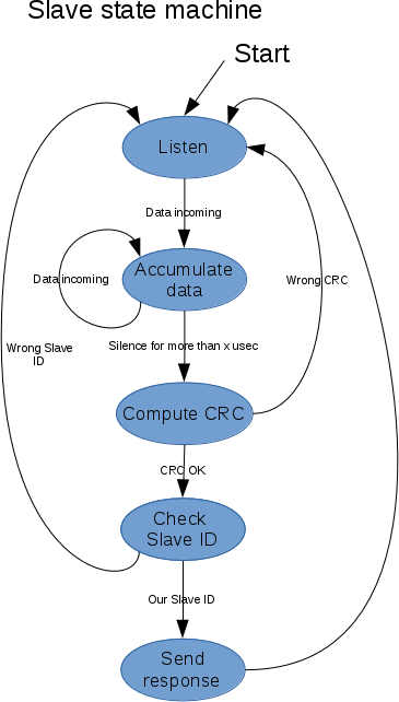
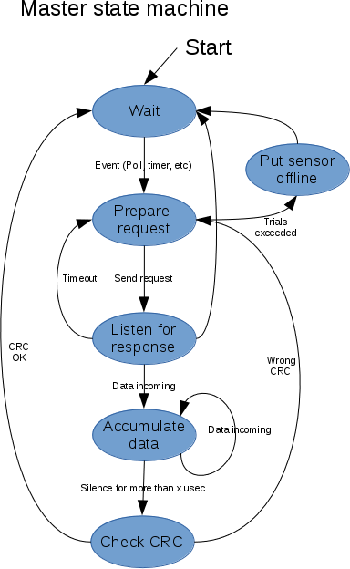
In order to communicate between the nodes, something similar to modbus could be used. Modbus has the inconvenient of having a big overhead per packet and is used in systeme where the master need to access content of register of slaves. It's not designed with firmware upgrade of slaves in mind for example.
The frames will have the following format:
- Slave ID is a configurable id (through DIP switch or jumper) located on each sensors.
- The content is then application defined
Informations
Schematic and prototyping code can be found at https://github.com/clementleger/calaos_plc_io_doc
Application note for reading RS485 bus with STM32 processors :


